Radiant Energy Antenna System
Radiant Energy Antenna System
Building the Radiant Battery Charger
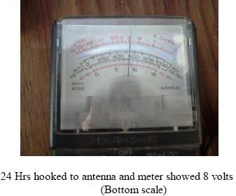
I must preface this by saying that after setting this up I was VERY disappointed in the results I got. I couldn’t get the dead battery to take more than 8 volts charge in the first 24 hours, which was the controlled test I wanted to run. Then to really rub it in, on my third day of writing this I received a copy of the new book by Tom Bearden and John Bedini titled Free Energy Generation, 20 Bedini-Bearden years , and was taken aback by the fact that the very same setup I show you here is also in their new book. Sure they drew it up differently than I was going to show it, but even having said that, there are things about this setup that are not told to you in Bearden’s book.
Those of you who have read the writings of the well known "Free Energy"? researchers like Bearden or Bedini know that they have tried to teach the general public about how simple it is to build this type system. Their biggest drawback is the fact that they are so far beyond what most people know about electrical circuits that they turn people off with their 15 letter high-tech wording. They understand what they mean when they say something, but most are simply blown away with the techno-word-ology they use. It gives people an uneasy sense of inferiority. The technology they have brought forth needs to be given to people in ways they can actually understand. Most people, given the right teacher, can grasp any concept.
Knowing exactly, precisely what’s going on in this setup and how it does what it does isn’t necessary to get results. However there are some things you should know about how the process manifests itself. I could write volumes on what is happening, but it would only serve to confuse. Different people call the same effect by different names; this only helps to further the confusion. After reading this and seeing for yourself how it functions, you’ll begin to get an idea of how the other systems I’ll write about actually work. They all have basically the same energy running them, some will utilize a mechanical method of input, other’s will use a natural input. So here goes, in the simplest language I know how to use.
In the "normal" way of charging batteries, we plug in our charger to our wall outlet and hook the leads up to positive and negative, this much makes sense to anyone, but the actions taking place in the inner workings of the battery are of major importance. In our "normal" scenario we are pushing (quite violently) the ions in the electrolyte (battery acid) backward, toward the negative sides of the plates. This causes heat and is classified as a "positive electrical event". This is why in the "normal" re-charging process the battery gets warm. Any action that causes heat to be generated is not generally considered to be radiant, ether, or any type of free energy. There are exceptions, of course, but we won’t go into those in this paper.
Our setup will work in a way that pulls the ions toward the negative plates of the battery. This is known in the scientific community as a form of implosion . Negative Electromagnetic energy converges, while positive energy diverges (expansion or explosion, rather than implosion). When hooked up to re-charge in this way the battery will be cold to the touch.
Nikola Tesla described the way he used energy pulses as a "disruptive discharge". Tom Bearden calls it "sharp gradients". But no matter what you call it, the basis of the technique is the same. That is to gather energy or voltage potential, in a capacitor and then abruptly discharge the stored energy across the load, which in our case will be a battery which will be gated from the negative (earth) side using a Silicon Controlled Rectifier (SCR) and a small neon bulb which will time the discharges as a kind of spark gap.
A Word about Capacitors
There are different kinds of capacitors you can use for this setup. Capacitors called Electrolytic are made for direct current (D.C.) applications only. In this system you can use Electrolytic or the Ceramic (disc) type. Electricity found in nature is usually D.C. Although D.C. actually can and usually does have a very high (Millions of cycles per second) frequency. Most instrumentation shows D.C. as a straight line at a given amount of voltage (actually 13.5 volts on a regular deep cell battery considered to be 12 volts) but is not really a steady source but is actually resonating at millions of cycles per second. The energy gathered by natural D.C. sources can be utilized locally where it is collected. When deciding what capacitor you will need, try to remember that the voltage ratings of a given capacitor is for reference if they are used in a "normal" circuit. When placing them into our system we aren’t limited to the voltage that a particular capacitor is rated at because we are using another type of energy in it. The value, in Microfarads, can be 3 to 10. In our setup shown here the capacitor is 10 Mfd.
Those of you who have studied the works of John Bedini know that in some of his references he states that his system of recharging provides a magnitude of negative voltage in the hundreds of thousands of volts. His systems don’t blow up or melt down because he tunes them to use negative energy, which was said earlier to be convergent energy, not normal divergent energy. This is how he gets away with using SCR’s rated at 800 volts, even though there could be hundreds of thousands of (negative) volts going through them. The same holds true for the capacitor used in the system.
Silicon Controlled Rectifier (S.C.R.)
The SCR we use will always be the same one regardless of the system it is put in. If it’s good enough for Bedini, it’s good enough for us. It is rated at 800 volts, 50 Amps. The Amps (current) rating isn’t important so we buy one rated in the lower current range, since current isn’t a factor. This SCR shouldn’t cost more than $5 or $6 (US). If you wish to, you can spend hundreds $$$ on ones that are rated with higher current values, but there’s no need to do so.
Where Do I Put It?
When figuring out where to put your system you will have to take into consideration what surroundings you have to work with. If you have a large farm, space won’t be a factor, but if you are living the city or suburbs, your choice of where to put the antenna will be limited. The standard to use when figuring your available potential, one would need to see what height you will place the antenna then multiply that height by 200 volts per meter of height from the ground. Some who have built these antenna systems use 300 volts per meter as their voltage calculation factor. Remember, the negative energy will be very forgiving even if you’re using what you think may be an under-rated capacitor.
The Procedure
The overall process is very simple and straightforward. Tesla showed us how to do this over 100 years ago. Whether we are mechanically providing the radiant potential or getting it from nature, this system and others like it are about to become widespread. Even if you don’t have the time to build it now, order the parts and have them so that when the time arrives you won’t be scrambling for them and you’ll be able to keep your water well going and provide some kind of comfort for yourself and family. Just get the parts listed and put it together or store them for future use.
Those of you who put the system together and have disappointing results as I did, don’t give up or throw out the parts. In the next pdf file I send out I will show you how to mechanically induce the energy using the same S.C.R. and capacitor and have a reliable system that I believe anyone can build.
Tinkering with it will be fun, and you’ll discover that if you have younger children, they will be interested in it also and that’s a good thing since this is probably what they will be using in the future. (Sooner than you may think)
Diagram
The length of the antenna can be any distance. The longer it is, the better you will have at finding the energy source. Generally it is not longer than 70 meters. The antenna can be any hieght. Use rule of 200 volts per meter off the ground. Antenna can be copper, romex, or steel; any size from 12 to 22 gauge will work.
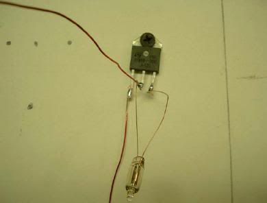
The NE 2 Neon lamp acts as a spark gap and times the impulses to the battery. It is sensitive to the voltage the voltage buildup and usually works nicely, even in other systems.
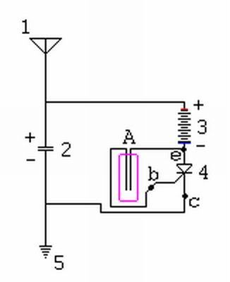
Here’s what we need as well as some simple explanations of what’s what and how it’s supposed to work.
Parts List
Here’s what the order form looked like. The following part numbers and prices are from www.mouser.com andare in U.S.$
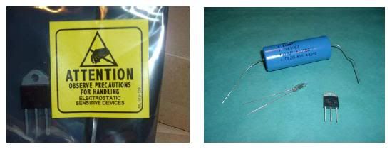
The Capacitor:
- 75-TVA1963
- Vishay-Sprague 600V 10uF
- $15.37
The SCR: 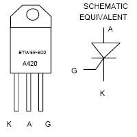
- 511-BTW69-800
- STMicroelectronics TO-3P 50 Amp 800 Volt
- $4.70
- The NE-2:
- 606-A2B
- Chicago Miniature T-2 65VAC .7mA NE-2V
- $0.50
- Sub Total: $20.57 Shipping: To Be Determined TOTAL: $20.57
Setup
Let’s Go Outside and Set It Up
We’ll find a place for the antenna, and then bring the wire down to the place where you’re going to actually charge the battery. If you’re trying this with a lead-acid battery make sure it is up to level with water or electrolyte. In this setup I’m going to use enameled copper wire for the antenna. I used #22 wire which is thin, but should handle what I’m trying to show here.
I’m going to attach the wire to a 10 foot tall (3 meter) board using staples and then nail the board upright against a fence, then string the wire along an existing fence or some other means of support. I will make this antenna 110 feet long, (33 meters) including the part nailed to the board that will stand up for the antenna height.
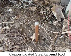
Then we hook up our parts as shown on the next page. Capacitor positive lead and the antenna lead directly to our battery junction (at the battery post) and the negative lead from our capacitor to the negative point at the rod we will hammer into the ground. I had the copper ground rod in my shop already but they are available at any good hardware store as well as any wire you may need.
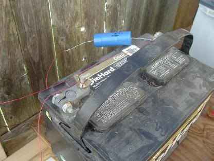
Then the Negative battery post to our S.C.R with our NE-2 across the leads as shown in the photo. (Middle lead to battery neg.) The left lead from the S.C.R. joins our other lead from the capacitor at our ground, via the rod I hammered into the ground.
NOTE
If you can actually see the NE-2 lighting up or flashing consider yourself lucky because you’ve found a great source of energy. Most of us probably won’t see it light up, and a few will occasionally see a flicker like a dying candle. THAT’S IT!!!!! Just measure the voltage of your charging battery before you hook it up to the setup. Also write down the time of day you started and track the recharging.
Variation on the setup
I want to also show a variation to this style setup. The reason I show this here is to give you an idea how you can setup an overshoot mechanism to dump excess energy should a thunderstorm or heavy rain come to your area while trying to use this setup to recharge a battery. I will say here and now that I have never tried this overshoot circuit, and as such can not offer any first hand experience regarding the effectiveness of the overshoot section.
The spark gaps on the left hand side of the drawing are further apart than the gap in the middle, and as such are actually used as a sort of resistor setup to act as an overshoot mechanism in case the larger spark gap receives too much energy from the antenna, like during a thunderstorm.
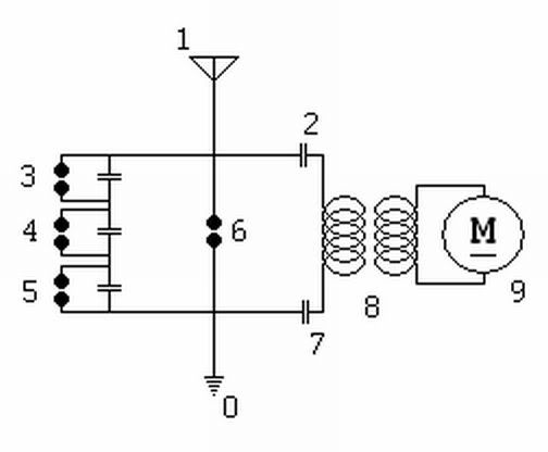
This is how the overshoot would be incorporated into the original S.C.R. style setup.
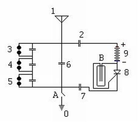
The larger spark gaps can be just simple nut and bolt sets drilled through a wooden board. Simply place them within a few thousandths of an inch of each other (.045 inch) Use a feeler gage to be sure you have the correct spacing. The NE-2 will be much closer than .045 so the gaps on the overshoot will work properly and not short your gathered energy to ground.
The capacitors used in the overshoot can be the same value as the main capacitor. They are in series so when one loads up it will let go its charge into the next and so on then the excess will be driven into the ground, unless it is dissipated by the spark itself. Of course you could just disconnect the setup with a switch at Point A above, that way it’s not grounded if foul weather approaches.
GOOD LUCK, LET THE GROUP KNOW OF YOUR SUCCESSES AND FAILURES!'
Hopefully you will not have the less than enthusiastic results I had. My results could have been the battery being absolutely worthless but I wanted to show that even using a worthless, old, dead battery it would still get some voltage in it.

